Esp8266 12e Relay Garage Door Opener

Esp8266 Nodemcu Wifi Iot Garage Door Opener Relay With Cayenne

Esp8266 Garage Door Monitor Hackster Io

Picture Of Esp8266 Nodemcu Wifi Garage Door Opener Relay Wiring Garage Door Opener Home Automation System Home Automation

Picture Of Esp8266 Nodemcu Garage Door Opener Relay Iot Fritzing Jpg Garage Door Opener Garage Doors Door Opener

Basics Project 066d Esp8266 Esp 12e Wi Fi Module Lolin Nodemcu V3 5v Relay Module Protected Io At Acoptex Com Acoptex Com

Picture Of Esp8266 Nodemcu Relay Wifi Garage Door Opener Garage Door Opener App Garage Door Opener Garage Doors

Warning it will oscillate if you fallow the other tutorials i tried the transistor and also using the opto isolator connected to ground but both pull the esp too close to ground it shorts out and will keep resetting itself.
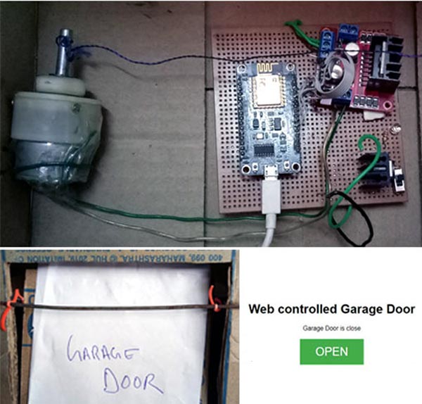
Esp8266 12e relay garage door opener. Complete circuit diagram for smart garage door opener is given below. The reason i wanted this was to be able to close my garage door remotely in case i left it open accidentally. I also use openhab home automation and included mqtt to be useful with that. Nodemcu is powered by a microusb 5v and steps it down to 3 3v for the esp8266.
Smart phone wifi controlled garage door opener with esp8266. Esp8266 wifi garage door remote. And it s never been easier for diyers to make their own home automation components. Dht22 am2303 temperature humidity sensor.
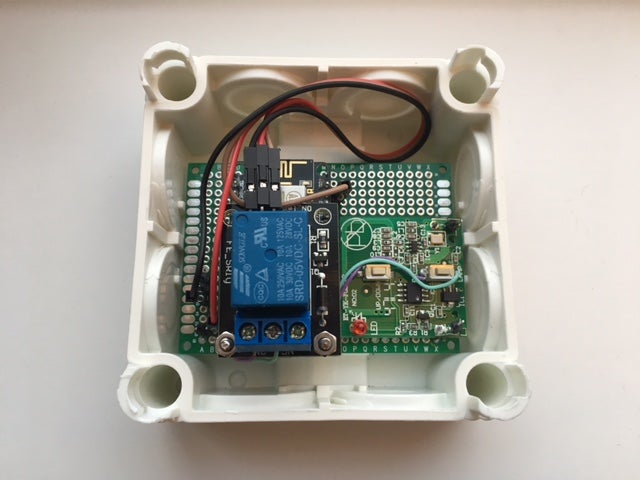
Always put the esp8266 gnd to the garage motor operner. I haven t been able to get the fake light to indicate if the garage door is open just yet. Smartthings triggers the relay which completes the circuit pushing the garage door opener button. Putting the lid back on and everything is hidden from view.
The vu offers usb power 5v which is required to power the relay. Esp8266 garage door opener. The garage door remote usually operates with 12v but gets the job done with 5v as well. Attached with adhesive tape.
My garage door opener comes with 4 terminals. In this project we will use an esp8266 with cayenne to control a garage door opener. Not long ago you had to shop online for smart home gizmos but now even the home improvement stores have a pret. Shelly 1 inside my garage door opener.
You can control anything with your phone nowadays. The two left most terminals are to control the. Connections for the circuit are given. Nodemcu esp 12e l298 motor driver or relay module.
You can switch the d1 d2 power and ground pins as you see fit. We use our garage more like a main entrance to the house because using the actual front entrance tracks a lot of dirt into the house due to the poor layout. 2 install a separate magnet switch also attention to the polarity when connecting the relay board to the garage opener. The shelly is connected to the garage door opener s logic board to toggle the state and also received 24v of power from it.
I used an esp8266 nodemcu with a 5v relay connected normally open directly to the terminals on the back of the garage door opener unit. Connecting it to vin or 3v will not work. By accessing pin vin we can still get 5v out to supply power to the 5v relay and the garage door remote. Shelly connected to the logic board of the garage door opener.
But i believe there is just one vu pin for the red relay cable on the nodemcu. Use your multi meter to check the input of your garage door. 1 make a circuit divider with 2 resistors.
Garage Door Opener Remote Web Interface With Esp8266 4 Steps With Pictures Instructables

Esp8266 Nodemcu Wifi Iot Garage Door Opener Relay With Cayenne Projects Made With Cayenne Mydevices Cayenne Community Arduino Arduino Wifi Coding

Esp8266 Mqtt Garage Door Opener Garage Doors Garage Door Opener Door Opener
Using Esp8266 Arduino And 2n2222 For Garage Door

Esp Easy On Esp8266 Controlling Hormann Garage Door Electronics Projects Electronics Projects Diy Esp8266 Projects

Picture Of Esp8266 Nodemcu Wifi Cayenne Garage Door Opener Relay Wiring Closeup Garage Door Opener Wifi Iot

Garage Door Opener Logs To Google Drive Garage Doors Bluetooth Gadgets Wifi Gadgets

Smart House Telegram Bot With Nodemcu Esp8266 Relay Ds18b20 Relay Esp8266 Projects Smart Home

Esp8266 Nodemcu Relay Wifi Garage Door Opener With Blynk Garage Doors Garage Door Opener Door Opener

Smallest Iot Home Automation Using Esp8266 01 Complete Iot Project Iot Projects Home Automation Iot

Garage Door Opener From Smart Phone Garage Door Opener Garage Doors Smartphone

Nodemcu 1 0v Esp8266 12e Arduino Projects Electronics Projects Diy Iot Projects

Amazon Com Teohk Esp 8266 Wifi Relay Module With Esp 01s Remote Smart Control Switch 5 12v Wireless Transceiver Computers Accessories